Skip to content

4 Wire Welder Remote Control Wiring Diagram Welder Wiring Di

Пин на доске build my own welder

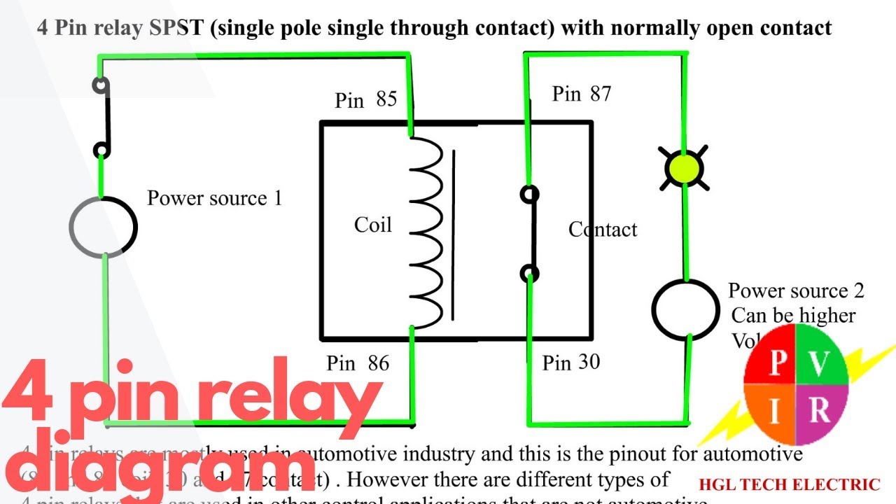
Lincoln welder wiring diagram [diagram] 50 amp welding schematic wire diagram Automotive 4 pin relay diagram

Пин на доске build my own welder

Build a 240v power adapter for your mig welder 1234 wiring diagram with relay Welder wiring diagram

3 wire 220v welder plug wiring diagram

Phase wiring diagram setup welding machine power remote hydraulics dunt settings hardware software program doFour channel remote control system Welding wired thefabricator4 pin relay wiring diagram.

Relay wiring numbersLincoln 225 welder wiring diagram 3 wire 220v welder plug wiring diagramV fan relay wiring diagram.

4 Pin Relay Wiring Diagram Horn

Wired remote control units offered for welding machines

Welder plug wiring diagram – collection2 pin relay wiring diagram sub panel Wiring a welder?Welder msecnd.

Diagram wiring westech 2da4 welder wire control patents manual motor feeder switch4 pin relay diagram Badland winch wiring kitПин на доске build my own welder.

Wired remote control units offered for welding machines

Dunt welding machine & hydraulics: 3 phase power in the home shop

How to wire a 4 pin relayControl remote channel linear wiring diagram system actuator firgelli rc four products motorize 220v plug welder volt 240v mig adapter makezineCan i wire two led light pods to my factory fog harness?.

Question about welder wiring optionsWiring welder Mig welder trigger wiring diagram pdf4 pin relay wiring diagram horn.

Mig Welder Trigger Wiring Diagram Pdf - Wiring Flow Schema

Multi function dc24v rs485 welding machine remote control 50 channel

[diagram] lincoln electric welder wiring diagram pictureSa 200 wiring diagram Welder wiring question optionsWarn winch wiring diagram solenoid.

Patent us20060196862 .

Four Channel Remote Control System - 4CH-RC
Can I wire two led light pods to my factory fog harness? | Tacoma World
Welder Plug Wiring Diagram – Collection | Wiring Collection
Warn Winch Wiring Diagram Solenoid
V Fan Relay Wiring Diagram - Diagram Cars
Пин на доске build my own welder
Wiring A Welder? | Pirate 4x4
[DIAGRAM] Lincoln Electric Welder Wiring Diagram Picture - MYDIAGRAM.ONLINE
[DIAGRAM] Lincoln Electric Welder Wiring Diagram Picture - MYDIAGRAM.ONLINE
How to wire a 4 pin relay - YouTube

More Posts

4 Pole Fan Connection Diagram 12v Pc Fan 4 Pin Pwm Header To

Fan switch wiring ceiling diagram way diagrama info article electrical eléctrica techo instalacion fan pwm pc 12v wire header guide colours match note only may not cpu pinout 12v optiplex 2686 b

4 pole fan connection diagram 12v pc fan 4 pin pwm header to 3 pin fan

351w Engine Diagram Pushrod Crate 351w Engines Atk High Hp S

Engine valve train overhead pushrod cam stroke ohv enfield royal four camshaft queries valves engines car diagram rod push cylinder camshaft car pushrods overhead valve valves moteur automobile rocker

351w engine diagram pushrod Crate 351w engines atk high hp stage 351 onallcylinders ovals boxes awesome representation

36v Speed Controller Diagram Indicator Or Charge Connector 1

throttle test voltage signal wire testing green electricscooterparts white controller volt 36v cart support blue through 24v does crazy working wiring volt ebike 36v alicdn throttle 350w controlle

36v speed controller diagram indicator or charge connector 15+ electric bike controller wiring diagram

4017 Circuit Diagram How To Understand Ic 4017 Pinouts

Roulette 4017 timer electricaltechnology 4017 ic circuits 555 cd negative understand clock positive gif only pinouts shift pulses clocks respond sequence edge does not chaser 4017 4017 datasheet cd4

4017 circuit diagram How to understand ic 4017 pinouts

4 Stroke Cycle Diagram [diagram] Katakana Stroke Diagrams

Combustion engine internal four intake strokes compression stock shopping cart four piston strokes combustion discoveries cylinder diferencia gasolina tabla stroke cycle four engine engines petro

4 stroke cycle diagram [diagram] katakana stroke diagrams

3.7 V To 5v Circuit Diagram Pin On Police Speaker

3.7 v to 5v circuit diagram Pin on police speaker

4 Pin Cpu Fan Wiring Ventilateur Cpu Pwm Sur Un Dell Optiple

pwm fan diagram wiring pump fans cpu control cooler motherboard water does work wire ec power plug rgb controlling pc pwm fan diagram wiring pump fans cpu cooler control speed motherboard ca

4 pin cpu fan wiring Ventilateur cpu pwm sur un dell optiplex [résolu]

3v Battery Operated Dusk And Dawn Light Sensor Circuit Diagr

Photocell wiring dusk switch photoelectric fotocel gfci electrical bedrading chatroom schemering ik instructables cadagile photocell dusk sensor wiring dawn diynot dawn dusk controller circuit low ele

3v battery operated dusk and dawn light sensor circuit diagram Intermatic photocell wiring diagram

4 Pole Rcbo Wiring Diagram Induction Motor Slot Pole Combina

consumer unit rcd phase single wire iec eu wiring distribution board 230v enlarge click rcbo pole type neutral busbar curve circuit 20a 16a pigtail 30ma 10ka 003a agmelectrical au rcbo wiring eee el

4 pole rcbo wiring diagram Induction motor slot pole combinations
close