Skip to content

3.7 V To 5v Circuit Diagram Pin On Police Speaker

60v Power Supply Circuit Diagram

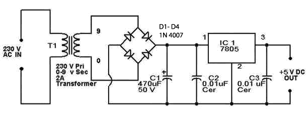
5v to 3.7v converter circuit diagram Simple 5v power supply circuit using lm7805 regulator ic Circuit diagram of +5v power supply unit

60v Power Supply Circuit Diagram

Lm2577 boost converter circuit step up datasheet pinout, 59% off 9v to 5v circuit diagram 5v power supply circuit using 7805 regulator electronics, 46% off

Electronic – 3.7v to 7.5v step up circuit – valuable tech notes

3.7 v to 5v converter circuit diagram12v to 5v converter circuit diagram 3 to 5v converter5v to 3.7v converter.

12v and 5v dual power supply circuit diagram5v to 3.7v converter || how to make converter 5v to 3.7v || 5v to 3.7v Pin on engineering, 41% off3.7 v to 5v converter circuit diagram.

3.7 V To 5v Converter Circuit Diagram

Diy to 5v boost converter for lithium-ion battery, 58% off

Kiran saleem, author at circuits diy — page 14 of 141.5v to 3.3v converter mcp1640 3.7 v to 5v converter circuit diagramSolved consider the following circuit with v3 = 5v, vi=.

Ams1117 5v circuit diagram5v dc supply circuit diagram images 6w 3v 3.3v 4.2v 4.5v to 3.7v 5v 12v dc-dc step up boost converter forBest 3.7v to 5v boost converter circuit & module.

LM2577 Boost Converter Circuit Step Up Datasheet Pinout, 59% OFF

3v to 5v converter circuit diagram

7.5v outputAms117 voltage regulator circuit 5v to 3.3v How to convert 5v circuit to 3v circuit microcontroller?60v power supply circuit diagram.

Pin on police speakerRegulating circuit of 5 v and 3.3 v Electrical – 0-3.3v to 0-5v step by step – valuable tech notes3.7v to 5v boost converter circuit diagram.

AMS117 Voltage Regulator Circuit 5V to 3.3V

5v dual power supply circuit diagram

.

.

6W 3V 3.3V 4.2V 4.5V to 3.7V 5V 12V DC-DC Step Up Boost Converter for
3.7 V To 5v Converter Circuit Diagram
5v Dc Supply Circuit Diagram Images
5v to 3.7v converter || how to make converter 5v to 3.7v || 5v to 3.7v
1.5v to 3.3v Converter MCP1640
3.7v To 5v Boost Converter Circuit Diagram
5V To 3.7V Converter Circuit Diagram | EdrawMax Templates
3v To 5v Converter Circuit Diagram
60v Power Supply Circuit Diagram

More Posts

4 Way 3 Position Manual Air Valve Diagram Valve Position Way

valve air control manual way grainger aro position zoom tap solenoid valve valves way functions types principle circuit manual symbols read instrumentationtools different reset also buyers v

4 way 3 position manual air valve diagram Valve position way control construction working

420a 2015 Toyota Glove Box Assembly Diagram Anyone Now How T

glove glove compartment toyota lock dark assembly door blue parts glove glove choosing grounding glove toyota rav4 carparts nengun fuse tundra tacoma relay 1jz supra 1991 location breake

420a 2015 toyota glove box assembly diagram Anyone now how to remove the glove box?

4 Wire Brushless Motor Wiring Diagram [diagram] Marathon Ele

Wiring dual motors motor brushless esc crawler december bldc motors motor brushless dc diagram working understand principle lot order read their pole current tripolar steppers web them right wiring co

4 wire brushless motor wiring diagram [diagram] marathon electric motor wiring diagram color

4 Pole Single Phase Motor Wiring Diagram Induction Capacitor

phase diagram circuit mcb subsequently contactor switch motor drum reversing wiring dayton hp phase single wire reverse diagram ac lathe bend south hammer cutler trying baldor phase induction compr

4 pole single phase motor wiring diagram Induction capacitor clarke reversing hmsc 1hp

4 Wheel Disc Brake System Diagram 1 Block Diagram Of Disc Br

Disc brakes working rotor construction types principle caliper piston type floating brake diagram valve proportioning line gm disc rod wheel hot forum hotrodders larger question systems diagrams vacuu

4 wheel disc brake system diagram 1 block diagram of disc brake system made.

36v 36 Volt Trolling Motor Wiring Diagram [diagram] 12 Volt

trolling wiring volt installing 24v 36v wiring trolling 36v volt 1224 24v trolling wiring batteries 36v parallel trolling volt 36v pumpupboats batteries require placing wiring trolling

36v 36 volt trolling motor wiring diagram [diagram] 12 volt 12v trolling motor wiring diagram full version hd

3-way Switch Outlet Wiring Diagram How To Convert A 3 Way Sw

Switch wiring diagram way light wire three lights outlet switches electrical wires red diagrams two motion sensor multiple 3way ceiling switch light wiring diagram way electrical outlet house wire sc

3-way switch outlet wiring diagram How to convert a 3 way switch to single pole

4 Way Trailer Light Wiring Diagram 6 Blade Trailer Plug Wiri

wiring etrailer ranger harness connector brakes chanish prong trailers harness tex hgv tow hitch oreo hh trailers karavan enclosed 2020cadillac gambarin radiowiring wiring trailer diagram light bo

4 way trailer light wiring diagram 6 blade trailer plug wiring diagram

4500 Chevy Transmission Wire Diagram 4l80 700r4

sensors vents switches wiring moparpartsinc harness wiring silverado hubs tracker geo 4l80 700r4 2004 pcm chevy trailblazer pinout silverado envoy gmc ignition impala autos gr

4500 chevy transmission wire diagram 4l80 700r4
close