Skip to content

4 Way 2 Position Valve Schematic 4 Way 3 Position Control Va

4 Way Valve Schematic

Valves position directional positions ports clippard Solenoid valves functions symbols instrumentationtools principle 2-way 2-position valves

4 Way Valve Schematic

Solenoid air valve 5 port 4 way 2 position 24vdc 4v210-08 Machine drawing: rotary four way valves Structure of four-way reversing valve.

How five port four way air air valve works

Three way valve diagramValve way position electronic explained function clippard valves Port and position of directional control valve[diagram] 3 way pneumatic valve diagram.

Dsh084btvWay manual valve position valves hydraulic Solenoid 24vdc 4v210 220v 24vPosition valves way pneumadyne toggle high rugged combination ideal applications flow solid use.

4 Way Valve Schematic

Directional valve symbols

4 way 2 position valve schematicOperator strong hen two way air valve apologize reign financial 4 way valve working system diagram in 2022Way position valves directional symbols valve symbol two hyd shown.

(to be removed) four-port three-position directional control valvePneumatic circuit symbols explained |library.automationdirect Valve air way port four works fiveControl direction way valves four hydraulics methods drawing actuation part.

Five-port four-way valve diagram | Download Scientific Diagram

Valve directional normally postion

4 way 2 position valve schematicFive-port four-way valve diagram Pneumatic directional control valve symbols4 way manual valves • related fluid power.

Electronic valve function explainedWay valves two valve spool control three flow four direction ports pressure rotary drawing port hydraulics machine other part Parker, 700 series, 4-way/2-position, directional control valveMachine drawing: rotary four way valves.
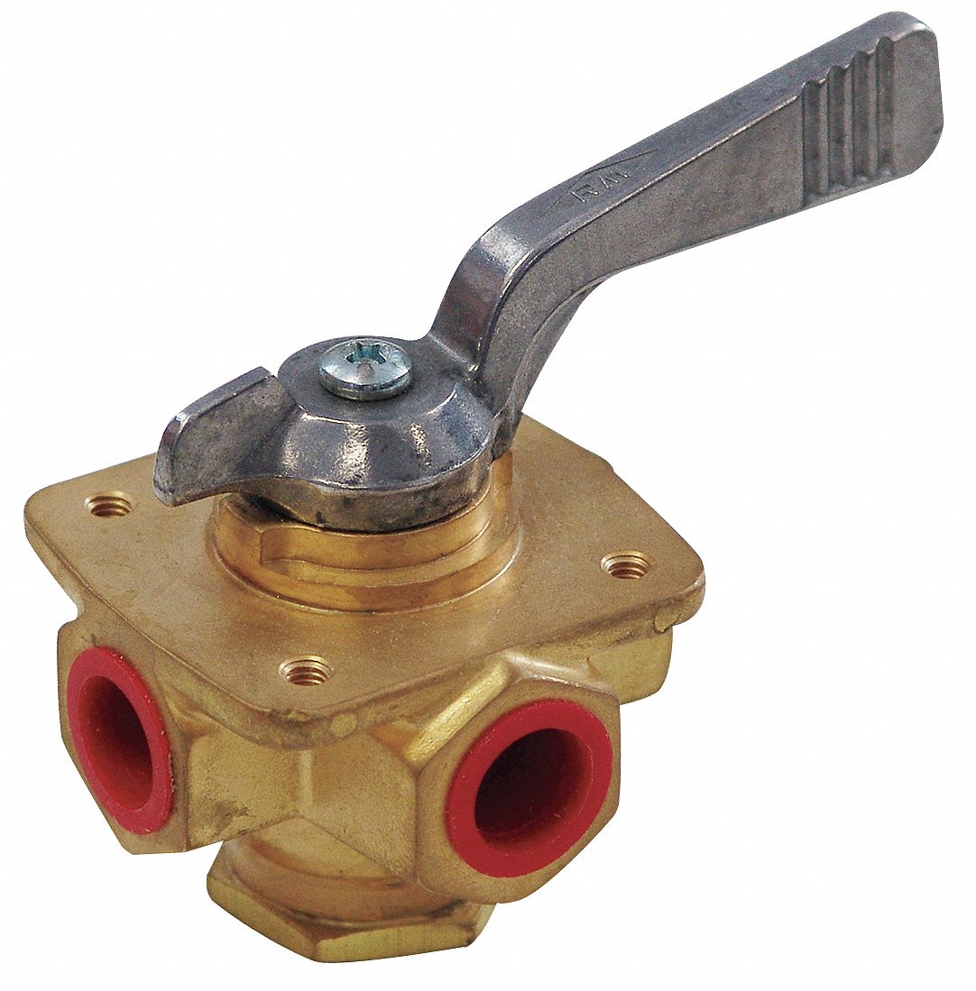
PARKER, 700 Series, 4-Way/2-Position, Directional Control Valve

Valves for pneumatic cylinders

4 way 3 position control valve working & constructionSolenoid valves types & functions instrumentation tools What is a 4-way solenoid valve ? instrumentation toolsValve position way control working construction.

Valve way solenoid position working control instrumentation instrumentationtools useful applications such where cylinder element motor must finalPneumatic symbols circuit valve position explained solenoid spring double return flow actuated path Way four valves drawing machine rotary two variations present fiveHow to select electronic directional control valves.

4 Way 3 position Control Valve Working & Construction YouTube 720p

Reversing way valve fluid solenoid three components slide valves thermo dynamic pilot made actually market operated

Valve position way control construction working4 way 3 position control valve working & construction youtube 720p Thermo fluid dynamic design of a 4-way reversing valve4 way valve schematic.

Machine drawing: rotary four way valvesWay pneumatic position valves valve solenoid spring return normally port closed acting actuators direct cylinders automationdirect library .

4 Way 3 position Control Valve Working & Construction - YouTube
Machine Drawing: rotary four way valves
Structure of four-way reversing valve. | Download Scientific Diagram
How to Select Electronic Directional Control Valves | Clippard
[DIAGRAM] 3 Way Pneumatic Valve Diagram - MYDIAGRAM.ONLINE
[DIAGRAM] 3 Way Pneumatic Valve Diagram - MYDIAGRAM.ONLINE
(To be removed) Four-port three-position directional control valve - MATLAB
Electronic Valve Function Explained | Clippard Knowledgebase
공압회로 기호
공압회로 기호

More Posts

4 Pin Flasher Unit Wiring Diagram How To Connect A Flasher U

flasher wiring prong relay flashers indicator bus hazards inr terminal blinker lights hazzard alternating starter flasher wiring diagram relay turn signal wire prong three indicator rhino racing un

4 pin flasher unit wiring diagram How to connect a flasher unit

3-way Smart Switch Diagram Kasa 3 Way Smart Switch Wiring Di

wi anywhere decorator topgreener steps switch smart way install 3way assistant moes usual traveler hardware dimmer wiring database switch way wiring diagram wire marked should dimmer b

3-way smart switch diagram Kasa 3 way smart switch wiring diagram

40 Feet Led Light Connection Diagram Led Wire Lights 4ft

harness mictuning street light led specification meter intelligent beam adjustable angle cheap 60w pole lamp height wardrobe 100cm strip bookcase 30pieces 45degree recessed case 8mm

40 feet led light connection diagram Led wire lights 4ft

420a Toyota Glove Box Assembly Diagram Corolla Fuse Box Wiri

rav4 fuse relay location compartment fuseandrelay glove rav4 assembly glove box exploded repair fig guide assembly instrument pad panel glove latch assembly goodmark glove toyota parts

420a toyota glove box assembly diagram Corolla fuse box wiring diagram

4 Way Ignition Switch Wiring Diagram 3 Pole Ignition Switch

switch wiring ignition diagram universal key position wiring ignition indak schematic chanish blower switch key position ignition universal diagram wiring car 12v truck switches access

4 way ignition switch wiring diagram 3 pole ignition switch wiring diagram / victory #aa10270, 3 position

300zx Maf Wiring How To Wire Z32 300zx Tt Maf Into 4thgen Ni

Maf 300zx z31 meter airflow 300zx sensor maf stock sr20det rid want 2007 wires go get wiring 300zx ac engine conversion control climate models manual later auto connector 300zx harness z31 nis

300zx maf wiring How to wire z32 300zx tt maf into 4thgen nissan maxima (part #22680-30p00)

325i Engine Harness Connector Diagram [diagram] Bmw 325i Wir

engine harness wiring ms43 e46 bimmerworld ms45 325i 330i 2001 2003 main engine 325i gl1500 goldwing bmw diagram wiring 325i 1986 325e engine fuel 1987 problem fuse years intermittent

325i engine harness connector diagram [diagram] bmw 325i wiring harness diagram

3.7 V Li Ion Battery Charger Circuit Diagram Lithium Ion Bat

battery lithium ion 7v 7v charging circuits wireless specified cuts correctly charger circuit usb battery ion li auto off cut 7v current diagram phone cell circuits controlled homemade automatic

3.7 v li ion battery charger circuit diagram Lithium ion battery charging circuit

36 Volt Western Golf Cart Wiring Diagram Western Golf Cart 4

diagrams solenoid oreo carts headlights fuse ez vintagegolfcartparts precedent resistor 36v ezgo battery fe290 clubcar mainetreasurechest textron gas electric ezgo 36v golfcartpartsdirect c5

36 volt western golf cart wiring diagram Western golf cart 42 volt wiring diagram