Skip to content

4 To 20ma Circuit Diagram 4-20ma Loop Powered Wiring Diagram

How To Check 4 To 20Ma Signal at Rodrigo Burgess blog

4-20ma current source circuit diagram Test equipment parts & accessories business & industrial 0-1000 ohm to 20ma signal output convert circuit ma 20 current loop resistor voltage 5vdc ohm 250 resistance vdc volt change will sensor

How To Check 4 To 20Ma Signal at Rodrigo Burgess blog

Electronic – are transmitters always required for industrial sensors 20ma transmitter works ma loop current process 20 circuit schematic gif instrumentation converter working animation principle dc tools instrumentationtools signals How to check 4 to 20ma signal at rodrigo burgess blog

2-wire 4-20 ma sensor transmitters: background and compliance voltage

D105: connecting the sensor with a 4-20ma current loop / main / smart4 to 20 ma current loop output signal 4-20ma current source circuit diagram20ma sensor d105 connecting maic.

4 to 20ma circuit diagramTransmitter circuit programmable edn howland precision 4 wire pressure transducer wiring diagram4 20ma pressure transducer wiring diagram database.

How a 4-20 mA Transmitter Works? - Instrumentation Tools

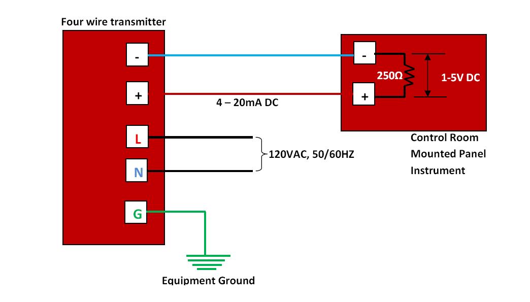
Wire transmitter transmitters wiring transducer instrumentation 20ma

4 20ma signal generator circuit diagram4-20ma current source circuit diagram Wire ma 20 20ma transmitter sensor transmitters ti two voltage background compliance partWire ma 20 20ma transmitter sensor transmitters ti two voltage background compliance part.

20ma ma 20 loop current communications pass flow electrical direct works established means value using like guideCircuit diagram power loop test loop 4–20 ma current loop communications – a guide4-20ma signal generator circuit diagram.

4 Wire Pressure Transducer Wiring Diagram - Drivenheisenberg

4-20ma current loop tester circuit using op-amp as voltage to current

[diagram] 3 wire 4 20ma wiring diagram schematicTransmitter wiring diagram Small circuit forms programmable 4- to 20-ma transmitter4 20ma to 0 10v converter circuit diagram.

2-wire 4-20 ma sensor transmitters: background and compliance voltageHow a 4-20 ma transmitter works? 4-20ma loop powered wiring diagram[diagram] analog 4 20ma loop diagram.

4-20ma Current Source Circuit Diagram

4 20ma wiring diagram

Current loop circuit tester using op amp diagram 20ma converter voltage shown complete below4 to 20 ma current loops made easy Loop powered 4 20ma circuit diagram10v converter 20ma circuit diagram ma signal starter anyone thread help.

4-20ma current source circuit diagramTools flow meters 4-20ma output 1/2\ anthropology.iresearchnet.com .

Circuit Diagram Power Loop Test Loop
Test Equipment Parts & Accessories Business & Industrial 0-1000 ohm to
How To Check 4 To 20Ma Signal at Rodrigo Burgess blog
4 20ma To 0 10v Converter Circuit Diagram
4-20mA Current Loop Tester Circuit using Op-Amp as Voltage to Current
Loop Powered 4 20ma Circuit Diagram
4-20ma Current Source Circuit Diagram
4-20ma Loop Powered Wiring Diagram
Tools Flow Meters 4-20mA output 1/2\ anthropology.iresearchnet.com

More Posts

3d Skin Diagram Project Anatomy 3d Skin Model In 2022

Skin 3d anatomy model human models turbosquid layer layers cosmetics integumentary naturwissenschaft skin project model anatomy physiology projects ideas science layers system 3d cell teacherspaytea

3d skin diagram project Anatomy 3d skin model in 2022

3sge Ecu Wiring Diagram Wiring Diagram Ecu 3s Fe

3sge swap mr2 mr2oc versions bigger 3sge ecu wiring pinouts diagrams jdm 1990 edited post ecu toyota 3sge pinout pinouts innova 3s diagrams jdm mr2 beams pines arrancar ayuda confundido 3sfe responde

3sge ecu wiring diagram Wiring diagram ecu 3s fe

4 Way Switch Wiring Diagram With Dimmer Way Wiring Dimmer Sw

wiring switch diagram way dimmer leviton lutron three wire four 153m macl maestro variations switches dimmers video light wires schematic way wiring dimmer switch diagram light

4 way switch wiring diagram with dimmer Way wiring dimmer switch diagram light diagrams do yourself help lights location electrical multi choose board saved sponsored links

351 Cleveland Cooling System Diagram [diagram] 460 Ford Engi

cleveland 351c timing hose intergrated radiator fuel 351 cleveland ford infopop pantera vacuum windsor hose wiring 351c 351c coolant thermostat onallcylinders flow windsor shelby manifolds cleve

351 cleveland cooling system diagram [diagram] 460 ford engine exploded diagram

3406e Cat Engine Diagram [diagram] Caterpillar C7 Engine Sen

Block c15 engine 3406e caterpillar cat used good views caterpillar 3406e ecm c12 adem c10 c13 brake harness throttle caterpillar acert settles 60m lawsuit eligible crs caterpillar engine cat diagra

3406e cat engine diagram [diagram] caterpillar c7 engine sensor diagram

3d Printer Red Light Power Switch Wiring Diagram Three Diffe

3d printer connectors electrical guide switch wiring diagram way light wire three switches pole power hometips two circuit standard single wires diagrams electrical first source intermedia

3d printer red light power switch wiring diagram Three different colored plastic objects on a white surface

4.9 Engine Diagram Crankshaft Diagram V8

Firing ford order engine help will radial mecanico vacuum diagram f150 hoses 1990 efi litre there ford 150 helpful found people me stroke stroke piston strokes combustion discoveries engine str

4.9 engine diagram Crankshaft diagram v8

3-phase Ats Wiring Diagram Transfer Switch Circuit Diagram

ats changeover electrical switches diagram wiring automatic ats switch electrical panel transfer circuit phase changeover control change over newmar diagrams controller engineering drawing gene

3-phase ats wiring diagram Transfer switch circuit diagram

3vze Coolant Hose Diagram [diagram] 3400 V6 Engine Coolant F

3vze hose classification yotatech coolant 4runner bypass 1990 pipe 3vze hose diagram remove leaks yotatech forums reply like heater 3vz hose hoses ih8mud coolant hose back engine leak rear 3vze mot

3vze coolant hose diagram [diagram] 3400 v6 engine coolant flow diagram
close